Introduction
This application note shows how to program and control the facility data link (FDL) on the DS2141A and DS2151. The ANSI T1.403 and AT&T TR54016 protocols used within receive and transmit FDL have been summarized.Because of expected future changes in FDL requirements, the DS2141A and DS2151 T1 controller makes use of software in the host to support the communications that occur on the FDL. Using the host's software to help control the FDL allows designs to be easily modified as the standards progress. The DS2141A and DS2151 implement in hardware the more basic functions of controlling the FDL, such as byte aligning to the FDL data stream. In current T1 networks there are two common protocols that exist on the FDL in the extended superframe (ESF) framing mode. One is defined in the American National Standards Institute (ANSI) document T1.403-1989 and the other is defined in the AT&T publication TR54016. Depending on the carrier used, either one (or both) of these protocols may be required. This application note details how a host would interface with the DS2141A and DS2151 to extract information from the FDL and insert data into the FDL. The user has the option on the DS2141A and DS2151 to either use its on-board RFDL and TFDL registers or to use the RLINK and TLINK pins to extract/insert data from/into the FDL data stream. This application note covers the usage of the RFDL and TFDL registers. The specifics of the two FDL protocols are not fully covered. (Note: All references to specific data values are in hexadecimal, which is denoted by the value enclosed within < >.) Please refer to the two ANSI documents mentioned for more details.
Receive FDL Control
The DS2141A and DS2151 contain an 8-bit register called the RFDL, which is automatically loaded with data from the FDL. A set of two match registers, RFDLM1 and RFDLM2, can be used to relieve the host from constantly polling the RFDL for any important data. If either of the values in the match registers corresponds to the current value in the RFDL, the host is alerted. Since most of the communication on the FDL follows the LAPD protocol, the DS2141A and DS2151 also contain a zero destuffer. The zero destuffer should always be enabled when using the RFDL to decode the FDL data stream. Also, when decoding the FDL, the DS2141A and DS2151 should have the ZBTSI (RCR2.6 = 0) and SLC-96 (CCR2.1 = 0) modes disabled. Figure 1 displays a flowchart of how to decode data off the FDL. The match registers are programmed to respond to the opening addresses of either a performance report message (PRM) in the ANSI T1.403 protocol or a request message in the AT&T TR54016 protocol. The DS2141A and DS2151 only match on the first byte following an opening flag of <7E>, and they automatically byte align to the incoming LAPD stream. The external controller normally waits for a match to occur. Once a match has occurred, the external controller waits for the RFDL register to fill, then reads it. The abort interrupt (SR2.1) takes on a new function once a match has occurred; it now reports when the closing flag <7E> is received. Hence, the external controller can monitor this flag during the extraction of data from the FDL to determine when all the data has been captured.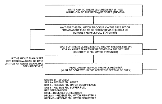
Figure 1. Receive FDL decoding.
If an abort flag is ever received (eight consecutive 1s), the SR2.1 bit is set to 1. An abort flag normally represents the beginning of an unscheduled (bit-oriented) message in the ANSI T1.403 protocol. The unscheduled message in ANSI T1.403 is a repeating 16-bit pattern of the form "...0CCCCCC011111111..." (Note: the abort flag is transmitted first; the C's represent one of 64 possible codewords). The unscheduled message is reported in the RFDL, as shown below.
| (MSB) | ? | (LSB) | ||||||
| RFDL | 1 | 0 | C | C | C | C | C | C |
It is possible for an unscheduled message to interrupt a PRM or a request message, thus the external controller should monitor the abort interrupt at all times.
Transmit FDL Control
The DS2141A and DS2151 contain an 8-bit register called the TFDL. Data that is to be transmitted onto the FDL is loaded one byte at a time into the TFDL register. Since most communication on the FDL follows the LAPD protocol, the DS2141A and DS2151 contain a zero stuffer to ensure that the data between the opening and closing flags does not resemble either an opening or closing flag. The zero stuffer in the DS2141A and DS2151 should only be enabled for the data bytes within the opening and closing flags. If the TFDL register is not updated, it retransmits the previous value contained in the register. When using the DS2141A and DS2151 to insert data into the FDL, the device should be set up to source the FDL from the TFDL register (TCR1.2 = 0), and both the ZBTSI (TCR2.5 = 0) and SLC–96 (CCR2.5 = 0) modes should be disabled. Figures 2 and 3 display two different flowcharts for inserting data into the FDL. Figure 2 details how to transmit an unscheduled (bit-oriented) message in an ANSI T1.403 environment. The specification calls for unscheduled messages to be transmitted at least 10 times. (Priority Messages are to be sent for at least one second). Figure 3 details how to transmit either a PRM according to T1.403 or a response message in the AT&T TR54016 protocol. According to ANSI T1.403, PRMs are to be transmitted once a second. The one-second timer in status register 2 can be used to determine when a PRM should be sent. In TR54016, response messages are only sent once a request has been received. When the FDL is idle and not sending any PRMs, the flag value of <7E> is to be transmitted.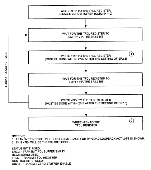
Figure 2. Transmit T1.403 unscheduled message.
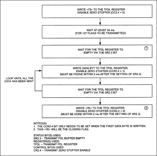
Figure 3. Transmit FDL coding.
DS2141A/DS2151 INFORMATION
For more information on programming and controlling the FDL on the DS2141A or DS2151, please contact the Telecommunication Applications support team via email telecom.support@dalsemi.com or call (972) 371-6555.For more information about the DS2141A or DS2151, please consult the respective data sheets available on our website at www.maxim-ic.com/telecom.
 電子發(fā)燒友App






評(píng)論