A real-time clock (RTC) provides a binary-coded-decimal (BCD) representation of the time and the date to the system's main processor. RTC accuracy is dominated by the characteristics of the external 32.768kHz "watch crystal." The main processor communicates with a Maxim RTC through a serial interface connection.
The RTC operates from the main supply and often uses a backup battery to power itself and keep accurate real time while the main power is absent. Most RTCs are designed to operate from a lithium backup battery for up to 10 years. Some RTCs have their own internal power switchover from the main supply to the backup battery. Simpler RTCs rely on microprocessor supervisors to provide the power switchover. Because the RTC runs from a 32.768kHz crystal, it requires currents typically under 1μA to run the RTC while in battery backup mode.
There are three main areas that need to be taken into account in the selection and the use of an RTC for a specific application. System, hardware, and software considerations will each be analyzed here to provide a checklist for optimum RTC selection.
System Considerations
Serial Bus Interface
Maxim's RTCs provide a choice of three different serial bus interfaces: 2-wire (I2C compatible), 3-wire, and 4-wire (SPI compatible). Details of these interfaces are found in each respective Maxim RTC data sheet. Their main characteristics are summarized as follows:2-Wire (I2C Bus Compatible, Philips and Others)
- 2-wire; data in/data out (SDA); clock (SCL)
- Bus speeds from 100kHz to 400kHz
- Data format = MSB first, LSB last
- 3-wire; data in/data out (I/O); chip select (CS); clock (SCLK)
- Bus speeds from 500kHz to 5MHz
- Data format = LSB first, MSB last; CS is active HIGH
- 4-wire; data in (DIN); data out (DOUT); chip select (active-low CS); clock (SCLK)
- Bus speeds from 1MHz to 10MHz+
- Data format = MSB first, LSB last; CS is active LOW
Crystal Selection
There are two types of crystals used for RTCs: 6pF load and 12.5pF load watch crystals. Generally, an RTC that uses a 12.5pF crystal has a timekeeping current of 1.7X more than an RTC that uses a 6pF crystal (that is, 6pF RTC current = 300nA @2V whereas 12.5pF RTC current = 500nA@2V). Timekeeping current is that measured when there is no serial bus activity and the RTC is only using current to run its 32.768kHz oscillator and count real time. A standard, low-cost, 50ma-hr, lithium, backup battery powers an RTC with timekeeping current of less than 570nA for up to 10 years.A 12.5pF load crystal oscillator is somewhat more stable and less susceptible to noise and PCB layout stray capacitance than a 6pF load crystal oscillator. This is partially due to the capacitance from each crystal pin to ground, internal to the RTC, which is 25pF per pin for the 12.5pF crystal RTC and 12pF for the 6pF crystal RTC.
There are also inventory issues for 32.768kHz watch crystals. Load crystals at 12.5pF are readily available through many distributors. In contrast, load crystals at 6pF are not as readily available and can require a minimum-quantity order to be purchased. Check with your local supplier for availability and price.
It's important to use the correct specified crystal with an RTC, because the wrong crystal can cause as much as a 100ppm error in the 32.768kHz oscillator frequency, which translates to a 4.3-minute error over a one-month period. In addition, the wrong crystal can cause excessive timekeeping current or failure of the oscillator to start properly.
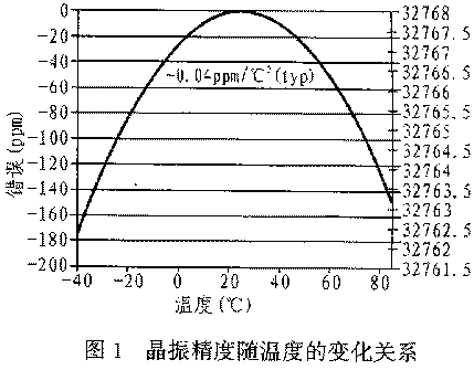
The dominant error in timekeeping for an RTC is the external crystal's errors. See Figure 1 for the typical temperature curve for 32.768kHz watch crystals.
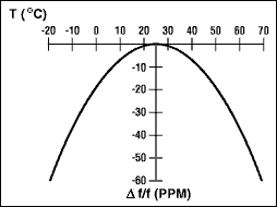
Figure 1. Parabolic temperature curve. To determine frequency stability, use the parabolic curve in Figure 1 and the following equation:
Δ? = ? × k × (T0 -T)2where:
| Δ ? | = change in frequency from +25°C (Hz) |
| ? | = nominal crystal frequency (Hz) |
| k | = parabolic curvature constant (-0.035 ±0.005ppm/°C2 for 32.768kHz watch crystals) |
| T0 | = turnover temperature (+25°C ±5°C for 32.768kHz watch crystals) |
| T | = temperature of interest (°C) |
For example, what is the worst-case change in oscillator frequency from +25°C ambient to +45°C ambient?
Δ?drift = 32,768Hz × (-0.04ppm/°C2 × (1 × 10-6)) × (20°C - 24°C)2 = -0.8192HzWhat is the worst-case timekeeping error per second?
Error due to temperature drift:
Δ?drift = {[1/[? = Δ?drift)/32,768Hz]] - 1s}/1sError due to 25°C initial crystal tolerance of ±20ppm:
Δ?drift = {[1/[32,768Hz - 0.8192Hz)/32,768]]- 1s}/1s = 0.00025s/s
Δ?initial = 32,768Hz × (-20ppm × (1 × 10-6)) = -0.65536HzTotal timekeeping error per second:
Δ?initial = {[1/[? = Δ?initial)/32,768]] - 1s} /1s
Δ?initial ={[1/[(32,768 - 0.65536)/32,768]] - 1s} /1s = 0.000020s/s
Δ?total =Δ?drift +Δ?initialAfter one month, that translates t
Δ?total = 0.000025s/s + 0.000020s/s = 0.000045s/s
Δ? = (31 days) × [24 hrs./day] × [60 min./hr.] × [60 sec./min.] × (0.000045s/s) = 120.528sTotal worst-case timekeeping error at the end of one month at 45°C is about 120 seconds, or 2 minutes (assumes negligible parasitic layout capacitance).
For more detailed information about crystal selection, refer to the application note, Considerations for Real-Time-Clock Crystal Selection.
Additional Features
In addition to the basic timekeeping features, there are RTCs that integrate other system features, such as microprocessor supervisory circuitry (Watchdog input, manual reset input, and reset outputs), an NVRAM controller, alarm functions (either polled through software or as an interrupt output pin), buffered frequency outputs, on-board scratch-pad RAM, battery backup input with switchover from Vcc to Vbattery, and a trickle charger for charging up a backup capacitor from Vcc. As higher levels of integration continue, there will be more features included inside RTCs.Depending on overall system real estate constraints, cost targets, and system performance, a determination can be made to either utilize several ICs combined with a simple RTC or use an RTC that integrates additional features.
Two final features for consideration are the RTC operating voltages and currents. Often the RTC voltage is specified in two different categories as timekeeping and operating. The operating voltage range is the range over which the serial bus interface is guaranteed to operate. The timekeeping voltage can be specified down to a lower voltage, because if the RTC is in a battery backup mode and just keeping time there is no need for the bus interface to be operational until the main supply returns. Correspondingly, there are individual currents associated with the timekeeping and operating modes.
Hardware Considerations
RTC crystal oscillators are low current and as such imply high impedance nodes on their crystal pins. In general, the lower the timekeeping current on an RTC, the more sensitive the crystal connections will be to noise. In addition, it is critical to minimize any stray parasitic capacitance when connecting the crystal leads to the RTC, because excessive stray capacitance will add to the overall crystal load capacitance and cause oscillation frequency errors. Proper bypassing and careful layout are required for optimum performance.When designing the printed-circuit board, keep the crystal as close to the crystal pins X1 and X2 as possible. Keep the trace lengths short and small to reduce capacitive loading and prevent unwanted noise pickup. Place a guard ring around the crystal and tie the ring to ground to help isolate the crystal from unwanted noise pickup. Keep all signals out from beneath the crystal and the X1 and X2 pins to prevent noise coupling. Finally, an additional local ground plane on an adjacent PCB layer can be added under the crystal to shield it from unwanted pickup from traces on other layers of the board. This plane should be isolated from the regular PCB ground plane and tied to the GND pin of the RTC. The plane shouldn't be any larger than the perimeter of the guard ring. Make sure that this ground plane doesn't contribute to significant capacitance (a few picofarads) between the signal line and ground on the connections that run from X1 and X2 to the crystal.
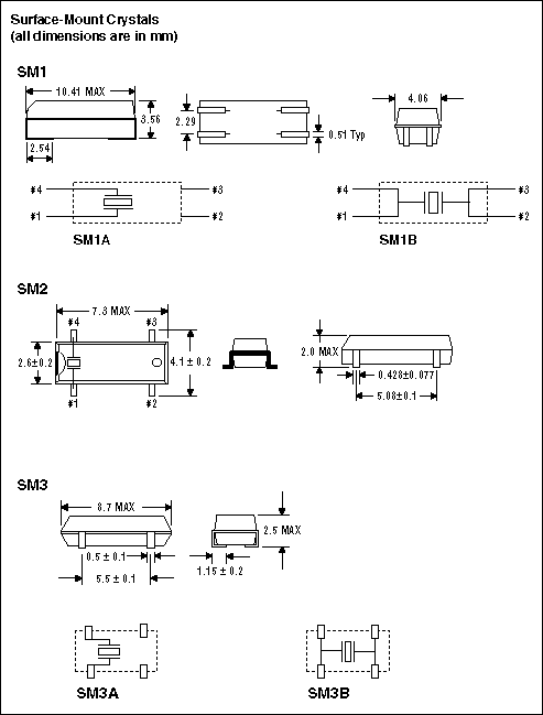
Recommended layouts for surface-mount crystals and through-hole, leaded crystals are shown in Figures 2 and 3, respectively.
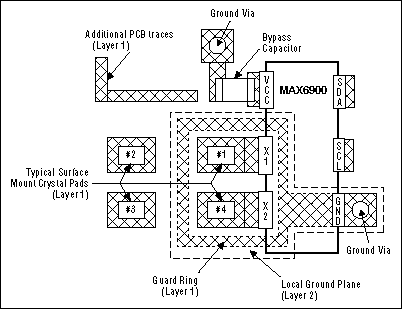
Figure 2. Surface-mount crystal PCB layout.
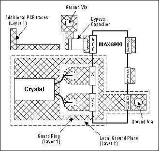
Figure 3. Through-hole crystal PCB layout.
Software Considerations
Oscillator Startup
Most low-current RTCs exhibit a startup time from 5 to 10 seconds depending on supply voltage and temperature. Maxim's RTCs contain a power-on-reset (POR) circuit to reset the timekeeping registers to initial values. The seconds register is initialized to zero seconds. After power is applied to the RTC and the system microprocessor or microcontroller is finished with its power-up initialization routines, a read from the seconds register to look for anything greater than zero seconds is verification that the RTC oscillator is operating properly. At this time, the initial system time settings can be entered into the timekeeping registers.Reading from the Timekeeping Registers
Maxim's RTC timekeeping registers (seconds, minutes, hours, date, month, day, year, and century) can be read with either a single read or a burst read. Because the real-time clock runs continuously and a read takes a finite amount of time, there is the possibility that the clock counters could change during a read operation, thereby reporting inaccurate timekeeping data. In Maxim's RTCs, each clock counter's data is buffered by a latch. Clock-counter data is latched by the read command. Collision-detection circuitry ensures that this doesn't happen coincident with a seconds-counter update, to make sure that accurate time data is being read. This avoids time data changes during a read operation. The clock counters continue to count and keep accurate time during the read operation.If single reads are to be used to read each of the timekeeping registers individually, then it will be necessary to do some error checking on the receiving end. The potential for error is the case when the seconds counter increments before all of the other registers are read out. For example, suppose a carry of 13:59:59 to 14:00:00 occurs during single-read operations of the timekeeping registers. Then the net data could become 14:59:59, which is erroneous real-time data. To prevent this with single-read operations, read the seconds register first (initial seconds) and store this value for future comparison. When the remaining timekeeping registers have been read out, read the seconds register again (final seconds). If the initial-seconds value is 59, check that the final-seconds value is still 59; if not, repeat the entire single-read process for the timekeeping registers. A comparison of the initial-seconds value with the final-seconds value can indicate if there was a bus-delay problem in reading the timekeeping data (the difference should always be one second or less).
The most accurate way to read the timekeeping registers is to do a burst read. In the burst read, the main timekeeping registers (seconds, minutes, hours, date, month, day, year) and the control register are read sequentially, in the order listed with the seconds register first. They must all be read out as a group of eight registers, with 8 bytes each, for proper execution of the burst-read function. All seven timekeeping registers are latched upon the receipt of the burst-read command. The worst-case error that can occur between the "actual" time and the "read" time is one second.
Writing to the Timekeeping Registers
The time and the date can be set by writing to the timekeeping registers (seconds, minutes, hours, date, month, day, year, and century). To avoid changing the current time by an incomplete write operation, the current time value is buffered from being written directly to the clock counters. Current time data is loaded into this buffer at the end of the write cycle. The clock counters continue to count. The new data sent replaces the current contents of this input buffer. Collision-detection circuitry ensures that this does not happen coincident with a seconds-counter update, to make sure accurate time data is being written. This avoids time data changes during a write operation. An incomplete write operation aborts the time update procedure, and the contents of the input buffer are discarded. The clock counters reflect the new time data beginning with the first one-second clock cycle after a complete write cycle.If single-write operations are to be used to write to each of the timekeeping registers, then error checking is needed. If the seconds register is one to be updated, update it first and then read it back and store its value as the initial seconds. Update the remaining timekeeping registers, and then read the seconds register again (final seconds). If initial seconds was 59, make sure it is still 59. If initial seconds was not 59, make sure that final seconds is within one second of initial seconds. If the seconds register is not to be written to, then read the seconds register first and save it as initial seconds. Write to the required timekeeping registers, and then read the seconds register again (final seconds). If initial seconds was 59, make sure it is still 59. If initial seconds was not 59, make sure that final seconds is within one second of initial seconds.
Although both single writes and burst writes are possible, the most accurate way to write to the timekeeping counters is to do a burst write. In the burst write, the main timekeeping registers (seconds, minutes, hours, date, month, day, year) and the control register are written to sequentially. They must all be written to as a group of eight registers, with 8 bytes each, for proper execution of the burst-write function. All seven timekeeping registers are simultaneously loaded into the clock counters at the end of the write operation. The worst-case error that can occur between the "actual" time and the "write" time update is one second.
Abstract: This application note describes real-time clock (RTC) and crystal selection criteria and proper layout techniques for connecting a 32kHz crystal to a RTC. Following these guidelines will prevent time errors and incorrect time due to crosstalk and improper crystal selection.
A real-time clock (RTC) provides a binary-coded-decimal (BCD) representation of the time and the date to the system's main processor. RTC accuracy is dominated by the characteristics of the external 32.768kHz "watch crystal." The main processor communicates with a Maxim RTC through a serial interface connection.
The RTC operates from the main supply and often uses a backup battery to power itself and keep accurate real time while the main power is absent. Most RTCs are designed to operate from a lithium backup battery for up to 10 years. Some RTCs have their own internal power switchover from the main supply to the backup battery. Simpler RTCs rely on microprocessor supervisors to provide the power switchover. Because the RTC runs from a 32.768kHz crystal, it requires currents typically under 1μA to run the RTC while in battery backup mode.
There are three main areas that need to be taken into account in the selection and the use of an RTC for a specific application. System, hardware, and software considerations will each be analyzed here to provide a checklist for optimum RTC selection.
System Considerations
Serial Bus Interface
Maxim's RTCs provide a choice of three different serial bus interfaces: 2-wire (I2C compatible), 3-wire, and 4-wire (SPI compatible). Details of these interfaces are found in each respective Maxim RTC data sheet. Their main characteristics are summarized as follows:
2-Wire (I2C Bus Compatible, Philips and Others)
- 2-wire; data in/data out (SDA); clock (SCL)
- Bus speeds from 100kHz to 400kHz
- Data format = MSB first, LSB last
3-Wire (Intel and Others, and I/O Port "Bit-Banging")
- 3-wire; data in/data out (I/O); chip select (CS); clock (SCLK)
- Bus speeds from 500kHz to 5MHz
- Data format = LSB first, MSB last; CS is active HIGH
4-Wire (SPI Bus Compatible, Motorola and Others)
- 4-wire; data in (DIN); data out (DOUT); chip select (active-low CS); clock (SCLK)
- Bus speeds from 1MHz to 10MHz+
- Data format = MSB first, LSB last; CS is active LOW
The choice of a serial interface is usually dependent on which microprocessor or microcontroller is available in the system. When the number of interface connections must be minimized, it is common to choose a 3-wire bus and "bit-bang" the interface through a couple of microcontroller ports.
Crystal Selection
There are two types of crystals used for RTCs: 6pF load and 12.5pF load watch crystals. Generally, an RTC that uses a 12.5pF crystal has a timekeeping current of 1.7X more than an RTC that uses a 6pF crystal (that is, 6pF RTC current = 300nA @2V whereas 12.5pF RTC current = 500nA@2V). Timekeeping current is that measured when there is no serial bus activity and the RTC is only using current to run its 32.768kHz oscillator and count real time. A standard, low-cost, 50ma-hr, lithium, backup battery powers an RTC with timekeeping current of less than 570nA for up to 10 years.
A 12.5pF load crystal oscillator is somewhat more stable and less susceptible to noise and PCB layout stray capacitance than a 6pF load crystal oscillator. This is partially due to the capacitance from each crystal pin to ground, internal to the RTC, which is 25pF per pin for the 12.5pF crystal RTC and 12pF for the 6pF crystal RTC.
There are also inventory issues for 32.768kHz watch crystals. Load crystals at 12.5pF are readily available through many distributors. In contrast, load crystals at 6pF are not as readily available and can require a minimum-quantity order to be purchased. Check with your local supplier for availability and price.
It's important to use the correct specified crystal with an RTC, because the wrong crystal can cause as much as a 100ppm error in the 32.768kHz oscillator frequency, which translates to a 4.3-minute error over a one-month period. In addition, the wrong crystal can cause excessive timekeeping current or failure of the oscillator to start properly.
The dominant error in timekeeping for an RTC is the external crystal's errors. See Figure 1 for the typical temperature curve for 32.768kHz watch crystals.
Figure 1. Parabolic temperature curve. To determine frequency stability, use the parabolic curve in Figure 1 and the following equation:
Δ? = ? × k × (T0 -T)2
where:
| Δ ? | = change in frequency from +25°C (Hz) |
| ? | = nominal crystal frequency (Hz) |
| k | = parabolic curvature constant (-0.035 ±0.005ppm/°C2 for 32.768kHz watch crystals) |
| T0 | = turnover temperature (+25°C ±5°C for 32.768kHz watch crystals) |
| T | = temperature of interest (°C) |
For example, what is the worst-case change in oscillator frequency from +25°C ambient to +45°C ambient?
Δ?drift = 32,768Hz × (-0.04ppm/°C2 × (1 × 10-6)) × (20°C - 24°C)2 = -0.8192Hz
What is the worst-case timekeeping error per second?
Error due to temperature drift:
Δ?drift = {[1/[? = Δ?drift)/32,768Hz]] - 1s}/1s
Δ?drift = {[1/[32,768Hz - 0.8192Hz)/32,768]]- 1s}/1s = 0.00025s/s
Error due to 25°C initial crystal tolerance of ±20ppm:
Δ?initial = 32,768Hz × (-20ppm × (1 × 10-6)) = -0.65536Hz
Δ?initial = {[1/[? = Δ?initial)/32,768]] - 1s} /1s
Δ?initial ={[1/[(32,768 - 0.65536)/32,768]] - 1s} /1s = 0.000020s/s
Total timekeeping error per second:
Δ?total =Δ?drift +Δ?initial
Δ?total = 0.000025s/s + 0.000020s/s = 0.000045s/s
After one month, that translates t
Δ? = (31 days) × [24 hrs./day] × [60 min./hr.] × [60 sec./min.] × (0.000045s/s) = 120.528s
Total worst-case timekeeping error at the end of one month at 45°C is about 120 seconds, or 2 minutes (assumes negligible parasitic layout capacitance).
For more detailed information about crystal selection, refer to the application note, Considerations for Real-Time-Clock Crystal Selection.
Additional Features
In addition to the basic timekeeping features, there are RTCs that integrate other system features, such as microprocessor supervisory circuitry (Watchdog input, manual reset input, and reset outputs), an NVRAM controller, alarm functions (either polled through software or as an interrupt output pin), buffered frequency outputs, on-board scratch-pad RAM, battery backup input with switchover from Vcc to Vbattery, and a trickle charger for charging up a backup capacitor from Vcc. As higher levels of integration continue, there will be more features included inside RTCs.
Depending on overall system real estate constraints, cost targets, and system performance, a determination can be made to either utilize several ICs combined with a simple RTC or use an RTC that integrates additional features.
Two final features for consideration are the RTC operating voltages and currents. Often the RTC voltage is specified in two different categories as timekeeping and operating. The operating voltage range is the range over which the serial bus interface is guaranteed to operate. The timekeeping voltage can be specified down to a lower voltage, because if the RTC is in a battery backup mode and just keeping time there is no need for the bus interface to be operational until the main supply returns. Correspondingly, there are individual currents associated with the timekeeping and operating modes.
Hardware Considerations
RTC crystal oscillators are low current and as such imply high impedance nodes on their crystal pins. In general, the lower the timekeeping current on an RTC, the more sensitive the crystal connections will be to noise. In addition, it is critical to minimize any stray parasitic capacitance when connecting the crystal leads to the RTC, because excessive stray capacitance will add to the overall crystal load capacitance and cause oscillation frequency errors. Proper bypassing and careful layout are required for optimum performance.
When designing the printed-circuit board, keep the crystal as close to the crystal pins X1 and X2 as possible. Keep the trace lengths short and small to reduce capacitive loading and prevent unwanted noise pickup. Place a guard ring around the crystal and tie the ring to ground to help isolate the crystal from unwanted noise pickup. Keep all signals out from beneath the crystal and the X1 and X2 pins to prevent noise coupling. Finally, an additional local ground plane on an adjacent PCB layer can be added under the crystal to shield it from unwanted pickup from traces on other layers of the board. This plane should be isolated from the regular PCB ground plane and tied to the GND pin of the RTC. The plane shouldn't be any larger than the perimeter of the guard ring. Make sure that this ground plane doesn't contribute to significant capacitance (a few picofarads) between the signal line and ground on the connections that run from X1 and X2 to the crystal.
Recommended layouts for surface-mount crystals and through-hole, leaded crystals are shown in Figures 2 and 3, respectively.
Figure 2. Surface-mount crystal PCB layout. 
Figure 3. Through-hole crystal PCB layout.
Software Considerations
Oscillator Startup
Most low-current RTCs exhibit a startup time from 5 to 10 seconds depending on supply voltage and temperature. Maxim's RTCs contain a power-on-reset (POR) circuit to reset the timekeeping registers to initial values. The seconds register is initialized to zero seconds. After power is applied to the RTC and the system microprocessor or microcontroller is finished with its power-up initialization routines, a read from the seconds register to look for anything greater than zero seconds is verification that the RTC oscillator is operating properly. At this time, the initial system time settings can be entered into the timekeeping registers.
Reading from the Timekeeping Registers
Maxim's RTC timekeeping registers (seconds, minutes, hours, date, month, day, year, and century) can be read with either a single read or a burst read. Because the real-time clock runs continuously and a read takes a finite amount of time, there is the possibility that the clock counters could change during a read operation, thereby reporting inaccurate timekeeping data. In Maxim's RTCs, each clock counter's data is buffered by a latch. Clock-counter data is latched by the read command. Collision-detection circuitry ensures that this doesn't happen coincident with a seconds-counter update, to make sure that accurate time data is being read. This avoids time data changes during a read operation. The clock counters continue to count and keep accurate time during the read operation.
If single reads are to be used to read each of the timekeeping registers individually, then it will be necessary to do some error checking on the receiving end. The potential for error is the case when the seconds counter increments before all of the other registers are read out. For example, suppose a carry of 13:59:59 to 14:00:00 occurs during single-read operations of the timekeeping registers. Then the net data could become 14:59:59, which is erroneous real-time data. To prevent this with single-read operations, read the seconds register first (initial seconds) and store this value for future comparison. When the remaining timekeeping registers have been read out, read the seconds register again (final seconds). If the initial-seconds value is 59, check that the final-seconds value is still 59; if not, repeat the entire single-read process for the timekeeping registers. A comparison of the initial-seconds value with the final-seconds value can indicate if there was a bus-delay problem in reading the timekeeping data (the difference should always be one second or less).
The most accurate way to read the timekeeping registers is to do a burst read. In the burst read, the main timekeeping registers (seconds, minutes, hours, date, month, day, year) and the control register are read sequentially, in the order listed with the seconds register first. They must all be read out as a group of eight registers, with 8 bytes each, for proper execution of the burst-read function. All seven timekeeping registers are latched upon the receipt of the burst-read command. The worst-case error that can occur between the "actual" time and the "read" time is one second.
Writing to the Timekeeping Registers
The time and the date can be set by writing to the timekeeping registers (seconds, minutes, hours, date, month, day, year, and century). To avoid changing the current time by an incomplete write operation, the current time value is buffered from being written directly to the clock counters. Current time data is loaded into this buffer at the end of the write cycle. The clock counters continue to count. The new data sent replaces the current contents of this input buffer. Collision-detection circuitry ensures that this does not happen coincident with a seconds-counter update, to make sure accurate time data is being written. This avoids time data changes during a write operation. An incomplete write operation aborts the time update procedure, and the contents of the input buffer are discarded. The clock counters reflect the new time data beginning with the first one-second clock cycle after a complete write cycle.
If single-write operations are to be used to write to each of the timekeeping registers, then error checking is needed. If the seconds register is one to be updated, update it first and then read it back and store its value as the initial seconds. Update the remaining timekeeping registers, and then read the seconds register again (final seconds). If initial seconds was 59, make sure it is still 59. If initial seconds was not 59, make sure that final seconds is within one second of initial seconds. If the seconds register is not to be written to, then read the seconds register first and save it as initial seconds. Write to the required timekeeping registers, and then read the seconds register again (final seconds). If initial seconds was 59, make sure it is still 59. If initial seconds was not 59, make sure that final seconds is within one second of initial seconds.
Although both single writes and burst writes are possible, the most accurate way to write to the timekeeping counters is to do a burst write. In the burst write, the main timekeeping registers (seconds, minutes, hours, date, month, day, year) and the control register are written to sequentially. They must all be written to as a group of eight registers, with 8 bytes each, for proper execution of the burst-write function. All seven timekeeping registers are simultaneously loaded into the clock counters at the end of the write operation. The worst-case error that can occur between the "actual" time and the "write" time update is one second.
 電子發(fā)燒友App








評(píng)論