Introduction to Protection Circuits
T3, E3, and STS-1 lines are used primarily in intra-building applications to connect one piece of equipment to another. Although the potential dangers from lightning strike and power-line cross are inherently less for intra-building lines than for externally-run lines (such as T1), various telecom standards organizations have established surge protection requirements for intra-building lines. For line interface designs to meet these requirements, protection networks must be used to direct high voltages and currents away from sensitive low-voltage CMOS devices.Surge protection networks are divided into two categories: primary and secondary. Primary protection is usually provided by gas discharge tubes or carbon blocks located at the point where the line enters the premises. Since primary protection only limits voltage surges to 1000VPEAK and power line cross to 600VRMS, secondary voltage protection is also necessary. Secondary protection provides additional voltage and current limiting to protect the LIU from damage.
Longitudinal (common mode) surge types are from tip to ground or from ring to ground, while metallic (differential) surge types are between tip and ring. Longitudinal surges are formed on the tip and ring conductors by lightning currents that enter the conductive shield of the cable. Because the outer conductor in T3/E3/STS-1 cables is grounded, it is only necessary to protect against metallic surges.
Recommended Protection Circuit
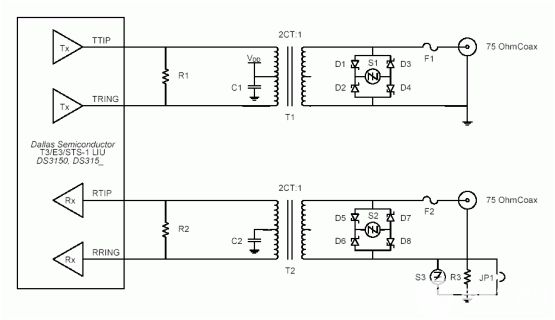
Figure 1 is Dallas Semiconductor's recommended metallic surge-suppression circuit for intra-building T3/E3/STS-1 applications. This circuit is designed to comply with the requirements listed in Table 1.Table 1. Applicable intra-building protection requirements
| TEST | VOLTAGE | CURRENT (Amp) | DURATION |
| Telecordia GR-1089-CORE | ? | ? | ? |
| Lightning Surge Test | 800VPEAK | 100 | 2 x 10μs |
| AC Power Test | 120VRMS 60Hz | 25 | 15 minutes |
| UL 60950 (formerly UL 1950) | ? | ? | ? |
| AC Power Test | 600VRMS 60 Hz | 40 | 5 seconds |
| AC Power Test | 600VRMS 60 Hz | 7 | 5 seconds |
| AC Power Test | 600VRMS 60 Hz | 2.2 | 30 minutes |
| ITU-T K.20 | ? | ? | ? |
| Lightning Surge Test | 1000VPEAK | 25 | 10 x 700μs |
| AC Power Test | 600VRMS | 2 | 200ms |
| ITU-T K.21 | ? | ? | ? |
| Lightning Surge Test | 1000VPEAK | 25 | 10 x 700μs |
| AC Power Test | 600VRMS | 2 | 200ms |
| AC Power Test | 230VRMS | 23 | 15 minutes |
| AC Power Test | 230VRMS | 1.15 | 15 minutes |
| AC Power Test | 230VRMS | 0.38 | 15 minutes |
| TIA/EIA-IS-968 (formerly FCC Part 68) | ? | ? | ? |
| Lightning Surge Test | 800VPEAK | 100 | 10 x 560μs |
| Lightning Surge Test | 1000VPEAK | 25 | 9 x 720μs |
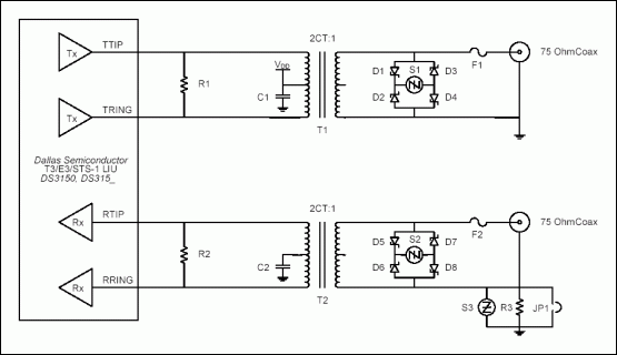
Figure 1. Recommended metallic surge-protection circuit for T3/E3/STS-1.
| Note 1: | The layout from the transformers to the network interface is critical. Traces should be at least 25mils wide and separated from other circuit lines by at least 150mils. |
| Note 2: | The trace impedance from the transformer to the device and the transformer to the network connectors should be matched to the line impedance of either 75Ω or 300Ω. |
The three main components used for protection are the fuse, the thyristor, and the diodes. The fuse protects the transformer against high-current conditions such as power-line cross. Typical fuses have a surge current rating above 100A for the different surge profiles. The fuses in Table 2 pass the 2 x 10μs, 10 x 160μs, 10 x 560μs, and 10 x 1000μs surges without opening. The thyristor is a solid state crowbar device that changes from an open circuit to a short circuit condition when the voltage across the device exceeds the switching voltage. The thyristor remains in the short circuit state until the current flowing through the device falls below a set holding current. In the short circuit state, excess current is routed to ground, thus stopping it from damaging the LIU device. The thyristor cannot be connected directly between tip and ring because its capacitance is large enough to distort the T3/E3/STS-1 signal. The diodes remove the thyristor capacitance from the tip/ring differential pair while still allowing the thyristor to perform its crowbar function.
Table 2. Recommended protection components
| COMPONENT | DESCRIPTION | PART | SUPPLIER | NOTES |
| D1-D8 | Ultrafast Power Rectifier | MURS160T3 | On Semiconductor | Surface-mount |
| MUR1100E | On Semiconductor | Through-hole | ||
| F1, F2 | 1.25A slow blow fuse | SMP 1.25 | Bel Fuse | |
| 1.25A slow blow fuse | F1250T | Teccor Electronics | ||
| C1, C2 | 0.05μF, 5% Tol, 10V | Kemet | ||
| R1, R2 | 330Ω, 1% TOl, 1/8W | Vishay | ||
| R3 | 50Ω, 1% Tol, 1/8W | Vishay | ||
| S1, S2 | 77V max transient suppressor | P0640SC MC | Teccor Electronics | |
| S3 | 6V max transient suppressor | P0080SC MC | Teccor Electronics | |
| T1, T2 | Transformer 1:2CT | PE-65968 | Pulse Engineering | Surface-mount |
| PE-65969 | Pulse Engineering | Through-hole | ||
| TG07-0206NE | Halo Electronics | Surface-mount | ||
| TD07-0206NE | Halo Electronics | Through-hole |
Suppliers List
| SUPPLIER | PHONE | FAX | WEBSITE |
| Bel Fuse, Inc. | (201) 432 - 0463 | (201) 432 - 9542 | www.belfuse.com |
| Halo Electronics, Inc. | (650) 903 - 3800 | (650) 903 - 9300 | www.haloelectronics.com |
| Pulse Engineering, Inc. | (858) 674 - 8100 | (858) 674 - 8262 | www.pulseeng.com |
| Teccor Electronics | (972) 580 - 7777 | (972) 550 - 1309 | www.teccor.com |
 電子發(fā)燒友App





評(píng)論