Introduction
The DS3903 is an ideal part for this type of application because the voltage allowed on the potentiometer terminals is 0V to 5.5V independent of the DS3903's supply voltage. This allows the DS3903 to be designed into the feedback loop of the MAX1776 without ensuring that the DS3903's supply level is always greater that the output voltage being generated. Additionally, the DS3903 provides 30PPM/°C stability when used as a voltage divider over temperature, which will minimize the effects of temperature on the performance of the circuit. For further reading on the use of digital potentiometers in power supply designs, AN226 discuses using digital potentiometers with step-up DC-DC converters.Benefits of Using a Digital Potentiometer
The primary benefit for using a digital potentiometer for creating an adjustable power supply is that they allow the automation of the calibration process. This is particularly true for 2-wire and 3-wire digital potentiometers because their digital interface is easily computer controlled. When interfaced to a test/measurement system, this allows the voltage supply to be calibrated without introducing a labor-intensive process into the production of the voltage supply circuitry. Other benefits of using digital potentiometers for this type of application include: nonvolatile (NV) position settings; small form factors; several potentiometers per package; low ratiometric temperature coefficient; and last but not least, they are relatively inexpensive.Using the DS3909 with the MAX1776
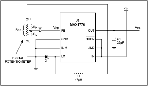
To generate an adjustable supply, the digital potentiometer is used to set the ratio of the output voltage VOUT, to the MAX1776's feedback voltage, VFB. This is done by connecting the output voltage to the high-side terminal of the potentiometer (H), the low-side terminal (L) to ground, and the wiper output (W) to the feedback pin FB, see Figure 1.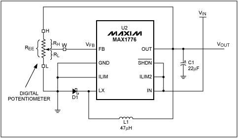
Figure 1. Using a digital potentiometer in the feedback loop with a MAX1776.
The output voltage will be set by adjusting the position of the potentiometer, which will cause the MAX1776 to raise or lower the output voltage until VFB is eventually maintained within the specified range of VFB for the MAX1776. The output voltage is shown as function of resistance in Equation 1, where VOUT is the output voltage, RL is the resistance from the wiper to ground, and REE is the end-to-end resistance of the digital potentiometer.
 |
Equation 1 |
 |
Equation 2 |
 |
Equation 3 |
 |
Equation 4 |
 |
Equation 5 |
Equation 2 and Equation 3 show REE and RL as a functions of ΔR and P, where ΔR is the incremental resistance increase per position, P is the current position setting, and the constant active-low P is the total number of positions for a given digital potentiometer. In the case of the DS3903, its potentiometers are 128 positions each.
Equation 4 is the result of substituting Equations 2 and 3 into Equation 1, then solving for VOUT and simplifying the expression. Equation 5, is Equation 4, assuming VFB for the MAX1776 is constant at its nominal value, 1.25V, and the DS3903 with 128 positions is used.
The circuit shown in Figure 2 is a simple circuit that allows the DS3903 to operate from the MAX1776's input voltage (VIN = 4.5V to 24.0V), and provide the feedback required to regulate the output. Key elements that make it possible for the DS3903 to operate in this circuit are:
- The DS3903's wide VCC supply range (2.7V to 5.5V) allows it to operate using a Zener diode to regulate its VCC supply. The DS3903's supply changes from approximately 2.7V to 4.3V as VIN is varied from 4.5V to 24V.
- The potentiometer signals of the DS3903 are allowed to operate from 0V to 5.5V as long as the DS3903 is powered, independent of the DS3903's VCC supply level. Most digital potentiometers require the potentiometer terminals to remain between 0V and VCC. This would require the output voltage of the MAX1776 to be below the digital potentiometer's supply voltage. Because the DS3903 does not have this requirement, it provides added flexibility in this type of application.
- The SDA and SCL pullups (R1 & R2) are operated off the same supply as the DS3903 (VDS3903), which also ensures that the part will work over a wide range of input voltages. If the DS3903 is disconnected from the 2-wire bus, the pullups should remain attached to SDA and SCL to prevent them from floating low.
- The DS3903 is NV, so once it has been used to calibrate the power supply it will remember its settings until changed at a future time, even if power is removed from the circuit.
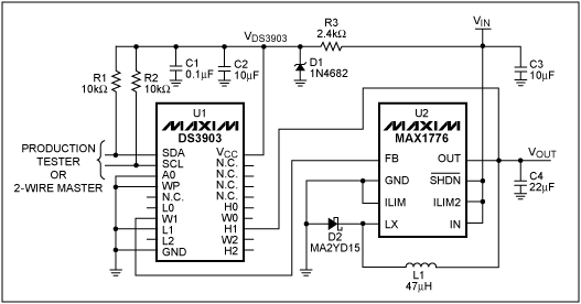
Figure 2. Using the DS3903 with the MAX1776.
The passive components shown used with the MAX1776 should be chosen based on the desired current limit inputs ILIM and ILIM2 in accordance with the Recommended Components selection guide shown in Table 3 of the MAX1776 data sheet. The values shown in this application note correspond with circuit 3 shown in this table. The circuit is able to provide 150mA DC, with a peak inductor current of 300mA. As mentioned in the introduction, other circuit configurations are available to supply up to 600mA of current.
Voltage Supply Accuracy, Precision, and Temperature Performance
Three parameters that are often used to determine a voltage supply's performance in an application are its accuracy, precision, and performance over temperature. This section shows some of the analysis required to determine how the digital potentiometer's integral and differential non-linearity and its temperature performance effect the voltage supply's ability to set its output voltage, calibrate its output voltage, and maintain its output voltage over temperature. These techniques can be applied to analyze the effect of placing any digital potentiometer into a similar DC-DC converter design.Supply Accuracy
Supply accuracy is being defined as error that can be expected in setting the supply to a particular voltage by calculating the digital potentiometer's position using Equation 5. Equation 5 assumes the MAX1776 has a typical feedback voltage (VFB = 1.25V) and ideal Integral Non-Linearity (INL) characteristics for the DS3903's potentiometer. In reality, the MAX1776's feedback voltage is a ±3% value, and the data sheet value for the INL of the DS3903 is ±1 LSB. Because the output voltage is determined by the multiplying VFB by the 1/ratio of the potentiometer, any error associated with INL is multiplied by the ratio of VOUT/VFB as well. Figure 3 shows the output accuracy as a function of the desired output voltage using both worst case and typical (based on the typical operating characteristic in the DS3903's data sheet) INL models for the potentiometer. This curve was calculated using Equation 4 with the worst case VFB (either 1.212V or 1.288V for low and high bounds respectively) and RL adjusted by ±1 LSB or the typical INL value of ±0.090 LSB. The output voltage's accuracy in most cases will not be important because the potentiometer's precision will be what effects the supply's accuracy after calibration.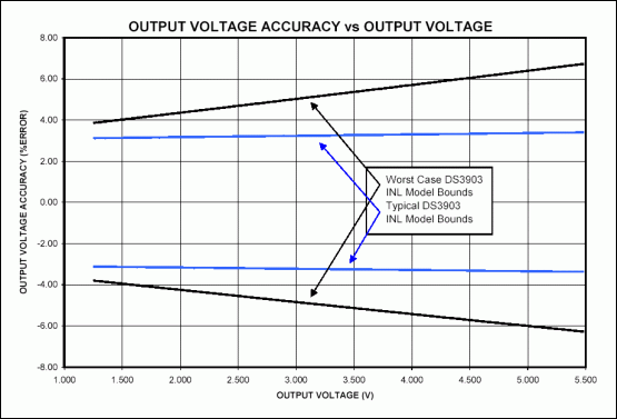
Figure 3. Output voltage accuracy as a function of desired output voltage.
Supply Precision
Supply precision determines the resolution that can be used to calibrate the supply to the desired output voltage. To analyze supply precision, VFB is assumed to be constant for a given part, and the quantizing error due to the discrete steps of the digital potentiometer including differential non-linearity (DNL) is evaluated. It must be assumed that either the worst case or typical DNL will always affect the discrete step about the desired voltage. Figure 4 shows the effects of DNL on supply precision.To calculate a supplies precision, Equation 1 is used, and RL will be adjusted to account for the DNL such that RL ± DNL causes an increased quantization interval. The calibration error is ? the quantization interval. Figure 5 shows the example circuit's (Figure 2) worst case calibration error as a function of the output voltage.
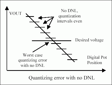
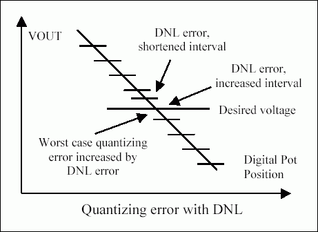
Figure 4. Analyzing supply precision considering quantization error and DNL.
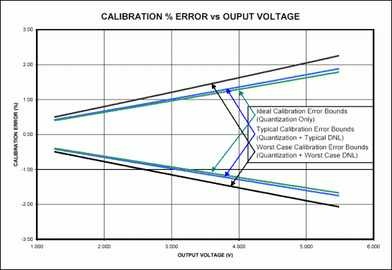
Figure 5. Calibration error due to supply precision as a function of the desired output voltage.
Temperature Performance
One of the advantages of using digital potentiometers in this type of a feedback loop is that digital potentiometers provide very good performance over temperature when they are used as voltage dividers. This is a direct result of the fact that the materials that make up the resistive elements within a digital potentiometer are matched within a single die. Looking at the VOUTPUT ACCURACY vs. TEMPERATURE typical performance curve in the MAX1776's data sheet, it shifts approximately -1.1% to +0.7% over the -40°C to +85°C temperature range. Most all of Dallas Semiconductor's digital potentiometers provide ±30PPM/°C temperature stability when used as a voltage divider. If the worst case scenarios are analyzed, the DS3903 will only add another 0.2% (30PPM/°C x (25°C - (-40°C)) = 1950PPM = 0.195%) error to the temperature performance of the circuit. Typically the DS3903's voltage divider temperature coefficient is approximately 15PPM/°C, so this effect would only typically cause a 0.1% change in the output voltage. When compared to external resistors that will each have their own temperature coefficients, the digital potentiometers are generally superior.Techniques to Improve the Circuit's Precision
With the design shown in Figure 2, only 99 of the 128 positions will produce output voltages under 5.5V. A simple improvement that dramatically improves the circuit's precision is to add resistors between the potentiometers low terminal and ground, and the high terminal and output voltage, see Figure 6. By calculating intelligent values for R1 and R2, it becomes possible to use all the positions of the potentiometer to adjust the output voltage over a smaller range (e.g. all 128 positions adjust between 3.0V and 3.6V). Because there will be more positions of adjustment working over a smaller range, the precision of the circuit is greatly enhanced. One thing that must be carefully accounted for is that REE has a wide tolerance. Generally digital potentiometers specify REE as ±20%, and additionally REE will shift over temperature.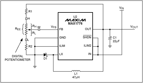
Figure 6. Improving the circuit's precision by adding external biasing resistors.
Another easy way to improve the performance of the circuit is to choose a digital potentiometer that has more positions such as the DS1845. The upside of choosing the DS1845 is that it offers 256 positions instead of 128. The downside of choosing the DS1845 is that it requires that the potentiometers be operated within the supply level of the DS1845. Thus, the circuit may have to be operated from a regulated 5V supply, and require that the output voltage is less than 5V. This may be practical in some instances, and it is an easy way to adapt the circuit to specific needs.
 電子發(fā)燒友App










評(píng)論