An LED Target-Practice Game Uses the MAXQ2000 and MAX7312
Abstract:?This application note is an LED target-practice game. The game demonstrates the capabilities of the MAXQ2000 microcontroller (MAXQ20 core) and the MAX7312 port expander. All the firmware required to interface the two devices is provided.
Introduction
This application note provides all the firmware required to interface the MAXQ2000 microcontroller (MAXQ20 core) to the MAX7312 16-bit port expander. The application example is an LED target-practice game. The example assembly program was written and assembled specifically for the MAXQ2000 using the free IAR Embedded Workbench? IDE version 2.10A.Hardware Overview
The MAX7312 is a 2-wire-interfaced 16-bit I/O port expander with interrupt and hot-insertion protection. Using this application note and a MAX7312 EV (evaluation) kit, the user can create an LED target-practice game. The EV kit's red and green LEDs will quickly roll up and down. The game's objective is to press one of the pushbuttons when the red and green LED lights meet at the center.The MAX7312 EV kit consists of the MAX7312, the MAXQ2000 microcontroller, all required passive components, and a proven PCB layout. The MAX7312 EV kit schematics are shown in Figures 1 and 2.
For more information on the MAXQ2000 microcontroller, please order the MAXQ2000 EV kit. The MAXQ2000 EV kit contains a complete set of software, hardware, sample code, and documentation needed to start designing with MAXQ2000. Schematics for the MAXQ2000 EV kit are available in the data sheet.
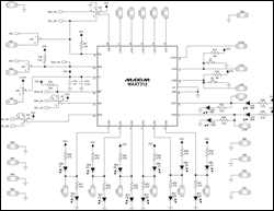
More detailed image (PDF, 256kB)
Figure 1. The MAX7312EV kit schematic, one of two schematics.
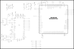
More detailed image (PDF, 292kB)
Figure 2. MAX7312EV kit schematic, second of two schematics.
Firmware Overview
The example firmware program (see below) communicates to the MAX7312 by bit-banging an I2C interface on the MAXQ2000's general-purpose input/output (GPIO) ports. The MAXQ2000's 20MHz system clock allows the bit-banged I2C interface to run at up to 400kHz. The user modifies the maxqi2c.h header file to select the speed of the I2C interface and which GPIO ports will be used as SDA and SCL. Please refer to application note 3588, "Software I2C Driver for the MAXQ2000 Microcontroller," for more information.Once the MAX7312 EV kit is powered on, the MAXQ2000 automatically detects the I2C address of the MAX7312. The program then starts to configure the MAX7312's port 1 GPIOs to create the LED lights' rolling effect. The port 2 GPIOs 8 and 9 are configured as input ports, and the firmware reads the states of the pushbuttons through those ports.
The game challenges the player to press a pushbutton when the red and green LED scrolling lights meet at the center. If the button is pressed when the LEDs meet, then MAXQ2000 microcontroller will detect it and all LEDs will flash indicating that the user wins the game.
Table 1 shows all of the I2C operations that are needed for this game application.
Table 1. I2C Operations
| I2C/SMBus Protocol | Application Purpose | Device Slave Address | Register Address |
| Read port 2 input register | Read the states of the pushbuttons | 0x40 | 0x01 |
| 01000000b | 00000001b | ||
| Write configuration registers to port 1 | Configure the I/O direction for port 1 | 0x40 | 0x06 |
| 01000000b | 00000110b | ||
| Write configuration registers to port 2 | Configure port 2 GPIOs 8 and 9 as input ports | 0x40 | 0x07 |
| 01000000b | 00000111b | ||
| Write output port register to port 1 | Turn LED lights on or off | 0x40 | 0x02 |
| 01000000b | 00000010b |
 電子發(fā)燒友App





評論