Sensors, such as temperature sensors, require galvanic isolation when they are mounted in "mechanically inconvenient" locations such as electrically noisy environments, poorly grounded environments, of instances where lack of isolation causes safety issues. New families of temperature sensors ease the design of isolated systems by virtue of a new simple, single-wire method with digitally-multiplexed outputs. These new devices also offer very low power consumption, simplifying the choices and cost of providing power to the isolated side.
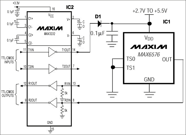
Isolating a temperature sensor with a unidirectional output is straightforward. An example is a temperature sensor with a frequency or period output, or a thermostatic switch output as shown in Figure 1. This circuit can take advantage of a new family of sensors such as the MAX6576, whose period is proportional to temperature, or the MAX6577 whose frequency varies with temperature. Maxim also provides the MAX6501 through MAX6507, a family of temperature switches (simple devices with outputs that become active at a pre-defined temperature) which could also be used in this circuit.
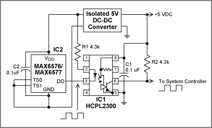
Figure 1. This simple isolated temperature sensor provides an output where either frequency or period is proportional to temperature. It can also be used with temperature activated switches (such as Maxim's MAX6501-MAX6507) for IC2.
Digital addressable sensors that have been available for some time, and prior articles, have demonstrated how to interface such devices on the I2C or SMBus (see references 1, 2). However the I2C or SMBus buses require two isolation circuits for their separate clock and data lines.
A new type of sensor family, the MAX6575H/L, has become available which enables the multiplexing of up to 8 sensors on a simple single-wire bi-directional digital bus. These sensors require a command signal from the processor, which they respond to after a pre-determined delay (which is covered in detail in their data sheets). The bi-directional bus requirement is readily satisfied by the same isolation method used for the I2C bus, with the simplification that only a single bi-directional isolator circuit is required.
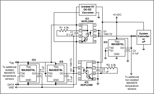
Figure 2. This circuit provides up to eight multiple "addressable" sensors on a single digital line. Sensors can be isolated or non-isolated, or a mixture of both.

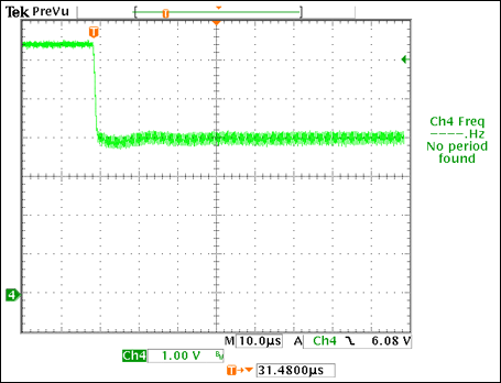
Figure 3. Typical communication sequence for Figure 2. Once the DO pin is pulled low and then released, control of the DO pin is transferred to the MAX6575L/H. The temperature conversion begins on the falling edge of the externally triggered pulse. The DO line is pulled low by the MAX6575 at a later time. That time is determined by the device temperature and the time select pins (TS1, TS0). The DO line remains low for 5Tμs, where T is the temperature in degrees Kelvin. The temperature of the device is represented by the edge-to-edge delay of the externally triggered pulse and the falling edge of the subsequent pulse originating from the device. The start pulse should be low for at least 2.5 μs (tStart).
The temperature, in degrees Celsius, may be calculated as follows:
T(°C) = [tDx(μs) / timeout multiplier(μs/°K)] - 273.15°K
The multiplier value for each sensor, determined by their TS0 and TS1 line selections (as well as exact model number, refer to the MAX6575 data sheet for details) is:
IC3, tD1: 5 μs/°K
IC4, tD2: 20 μs/°K
IC5, tD3: 80 μs/°K
Although the design of the isolator in Figure 2 is symmetrical, for the sake of this description the left side connects to the isolated slave devices while the right side goes to the master (typically a microcontroller, microprocessor, or digital line to a computer). If the computer takes the right line low, the photo diode in Opto 1 turns on the transistor in Opto 1, pulling the slave data line low. The transistor in Opto 1 pulls the data line down in such a way (via D2) that the photo diode in Opto 1 cannot be activated, which would return the signal around the loop and latch the circuit if it happened. Data transfer in the opposite direction functions identically except via Opto 1. The circuit of Figure 2 will drive a total of 8 MAX6575 devices in any combination of isolated or non-isolated sensors. Also shown is a block depicting the isolated power supply or an alternative battery power.
References
- "Isolate Data Acquisition On a Bidirectional Bus" by Jerry Steele in Electronic Design, November 6, 1995.
- "Temperature Sensor Uses I2C Isolator" by Jerry Steele, EDN, June 6, 1996.
 電子發(fā)燒友App






評(píng)論